I now have the AWA 1R64837 output limiting module (thanks again, Stephen C). I'll post some photos and a schematic as soon as I get around to doing it, but for those who lurk with interest ....
Its NOT one of the classic 6U high gunmetal compressors you think of when you say AWA limiter (if it were, would Stephen have given it away?), but it IS all discrete. No ICs, just heaps of transistors. Its an old 10 inch PCB with a 25pin connector out the back, designed to be inserted into a console (if there is a standard pin out for this sort of thing, could someone let me know?), and so no onboard trannies either. Just 2 controls: an in/out switch and an attenuation pot marked from -2 to 2 db. There are then 8 PCB mount pots labelled COARSE, FINE, METER, EXT METER, DIST, D.C., +PEAK and 20V.
More to follow .....
- It is currently Sat Apr 20, 2024 7:14 pm • All times are UTC + 10 hours [ DST ]
AWA limiter restoration
Moderators: rick, Mark Bassett
9 posts
• Page 1 of 1
AWA limiter restoration
![]() by chris p » Thu Jan 18, 2007 11:11 am
by chris p » Thu Jan 18, 2007 11:11 am
-

chris p - Frequent Contributor

- Posts: 882
- Joined: Tue May 10, 2005 6:15 pm
- Location: Sydney, NSW

![]() by chris p » Mon Jan 22, 2007 3:23 pm
by chris p » Mon Jan 22, 2007 3:23 pm
Ok folks, this is my first go at the circuit. Bear in mind there is zero documentation on this. The MR boxes are, I think, a sort of diode, but I'm still working on IDing the part.

If one of you career jockeys (ie you do this for a living) would like to help me turn this into a useful compressor/limitor for my preamp, I'm happy to throw some money at it. I'm after the expertise to reverse engineer the id of the pinouts on the connector plus what all those control pots actually do plus what can be done to make it more compressor like. PM me with an idea of costs.
Alternatively, if anyone knows an ex-AWA engineer to whom I could speak .....
-
chris p - Frequent Contributor
- Posts: 882
- Joined: Tue May 10, 2005 6:15 pm
- Location: Sydney, NSW


![]() by chris p » Tue Jan 23, 2007 4:34 pm
by chris p » Tue Jan 23, 2007 4:34 pm
I'm in the process now of double checking the circuit paths, and then I'll add in the resistor values and tranny ids. Thanks for looking, though, Rob. I also still need to put up some photos, Chris Mdfu, though I want to clean some of the dirt away first.
-
chris p - Frequent Contributor
- Posts: 882
- Joined: Tue May 10, 2005 6:15 pm
- Location: Sydney, NSW
![]() by chris p » Wed Jan 24, 2007 9:33 pm
by chris p » Wed Jan 24, 2007 9:33 pm
OK, here we go.
First, some pics


The circuit diagram has also been updated to show resistor values and transistor ids where possible. The VRs carry no marking, and (as you might expect) I get some pretty wild readings off a multimeter when measuring resistance in circuit (never a good idea, but I'm loathe to desolder them unless I have to).

As before, any assistance with this project greatly appreciated, and I'm not necessarily asking for it to be free (although don't get me wrong: free is good provided its right!)
First, some pics
The circuit diagram has also been updated to show resistor values and transistor ids where possible. The VRs carry no marking, and (as you might expect) I get some pretty wild readings off a multimeter when measuring resistance in circuit (never a good idea, but I'm loathe to desolder them unless I have to).
As before, any assistance with this project greatly appreciated, and I'm not necessarily asking for it to be free (although don't get me wrong: free is good provided its right!)
-
chris p - Frequent Contributor
- Posts: 882
- Joined: Tue May 10, 2005 6:15 pm
- Location: Sydney, NSW
![]() by JLM Audio » Wed Jan 24, 2007 11:58 pm
by JLM Audio » Wed Jan 24, 2007 11:58 pm
HI Chris
This card is part of a AWA BIG1 fet compressor which I have the full manuals for so no need to draw the circuits. Shown is two that we highly modified a while back to make them useful for recording instead of transmitter overload protection like they were designed to be used for.
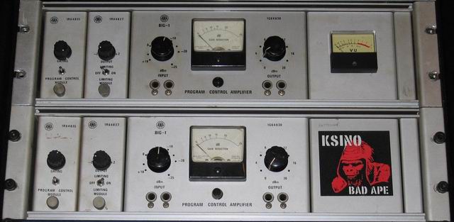
This card is part of a AWA BIG1 fet compressor which I have the full manuals for so no need to draw the circuits. Shown is two that we highly modified a while back to make them useful for recording instead of transmitter overload protection like they were designed to be used for.
-

JLM Audio - Registered User

- Posts: 23
- Joined: Sun Sep 17, 2006 8:05 pm
- Location: Brisbane Australia
9 posts
• Page 1 of 1
Who is online
Users browsing this forum: No registered users and 1 guest