Help diagnosing fault in HT power supply

Are you building something? Share your resources with the locals - for more in depth D.I.Y. head to The Lab

Moderators: rick, Mark Bassett

Help diagnosing fault in HT power supply

Postby Alistair » Tue Jul 03, 2012 11:15 pm

So after sitting on it for about a year, I'm finally getting around to racking up one of the Trimax A55 line amps that have been going around.
Myles suggested a possible power supply (http://cgi.ebay.com.au/ws/eBayISAPI.dll ... 612wt_1026) which I ordered the other week and fired up. It was working fine for about 30 mins, then suddenly stopped working. The high voltage line dropped from +130v down to 0-2v fluctuating.
I traced this back to the voltage regulator (MJE13005), which I've replaced. From there my supply has jumped from 0v up to 350v, and I can no longer control it with the potentiometer!
I've tested the other transistors in the circuit (MPSA42 type), and one was dead- I've replaced that too, but no change. Does anyone have any ideas for what could be stopping the voltage regulation from working?
Schem below- obviously the top half is the high voltage line, the bottom half is for the heater circuit which is working fine.


Image
Also, for anyone thinking of using this PS for the Trimax, I wouldn't recommend it. The soldering work is very very messy, and a few of the larger capacitors appear to be second hand, which is a little bizarre. Furthermore, after these problems I've been in touch with the seller, and he claims that whilst it can regulate down to +130v with his matching transformer, it's not a good idea.
Alistair McLean
Alistair
Frequent Contributor
 
Posts: 634
Joined: Fri Jul 16, 2010 11:35 am
Location: Melbourne

Re: Help diagnosing fault in HT power supply

Postby rob » Tue Jul 03, 2012 11:54 pm

do you have a transistor tester? If not do you know how to do a basic diode test between base and emitter plus base and collector? Check D1 is still a diode. Check the zener. Above all, double check that all parts of the supply are discharged before you work on it!
350V to 130V is a big drop and you will be wasting some serious heat in the pass transistor.

Also, you know you need -24V as well. And maybe +48V if you want phantom.
User avatar
rob
TRM Endorsed
TRM Endorsed
 
Posts: 1011
Joined: Tue May 10, 2005 9:16 pm
Location: Adelaide

Re: Help diagnosing fault in HT power supply

Postby Alistair » Wed Jul 04, 2012 12:13 am

Hi Rob,

Thanks for the reply. I'm currently trying to source a PT with 130-180v secondaries to reduce the work the circuit has to do.

I do have a separate PS with +24v and +48v. I've also learnt how to make a nifty slow start phantom circuit to protect the input tx, which is useful.
Some of the guys over at Groupdiy suggested that the schematic was an older way of writing tube schems, and I actually needed to tie the 0v of the 130v rail, and the +24v rail together, and use the 0v of the +24v rail as -24v (I hope that makes sense). It certainly wasn't my first thought of how to wire it up, but I do know the little tagstrip that was originally in the Trimax has 3 connections listed as +130, -130v/+24v and -24v, and the -130v/+24v is also connected to ground.

I've got basic transistor testing in my multimeter. I use this set of instructions http://www.stickycarpet.com/pinx/test.html, and all of the MPSA42's are fine. I'll test the rest of the diodes and the zener tomorrow and let you know how I go.
And yes- the cap discharge tool I made years ago for working on guitar amps has been getting a work out!
Alistair McLean
Alistair
Frequent Contributor
 
Posts: 634
Joined: Fri Jul 16, 2010 11:35 am
Location: Melbourne

Re: Help diagnosing fault in HT power supply

Postby rob » Wed Jul 04, 2012 11:07 am

you can certainly make the +24V a -24V by commoning the the +24V to the 130V 0V. If the 48V and 24V share a common reference or 0V then it can get tricky.
How i've done these:
I use a JLM 3rail PSU set up for +24V and +48V
I build a simple zener reg pass transistor using a TIP50 on a piece of vero board set to 130V.
I use a 230 to dual 12V transformer strapped for 24V to feed the JLM board
U use a second 12 V dual transformer with the 12V in parallel connected to the 24V from the first transformer. This gives me 115V ac on the primary side which feeds the HT board. Thus two mains transformers back to back.
All simple, cheap and using locally available parts.
The key here is that the common side of the JLM module is used as the input and output ground reference, allowing the 48V to be correct, BUT it is not the common side of the amp module. This is taken from the JLM +24V point which is taken also the HT 0V. Since the Trimax is transformer isolated in and out this works fine.

You also will probably find that your Trimax has been modified around the output pair to use 6AM6 tubes. This involves swapping the wiring on pins 2, 6 and 7. Usually R11 is linked out in this mod.
User avatar
rob
TRM Endorsed
TRM Endorsed
 
Posts: 1011
Joined: Tue May 10, 2005 9:16 pm
Location: Adelaide

Re: Help diagnosing fault in HT power supply

Postby Alistair » Wed Jul 04, 2012 1:03 pm

I've used some mnats psu boards that are great because the 24v and 48v lines are completely separate and don't share a common ground.
I saw the photos of the Trimax you fixed for Angus and saw the torroidals stacked, and assumed you'd used a high powered torroidal. Using two 12v+12v is a great idea!

Thanks for the info on the 6am6- I actually brought the circuit back to the schematic there, and have been having problems since doing so. I should have checked the pinouts first, I didn't realise the cathode and grids were different.

Thanks for your generosity of knowledge Rob!
Alistair McLean
Alistair
Frequent Contributor
 
Posts: 634
Joined: Fri Jul 16, 2010 11:35 am
Location: Melbourne

Re: Help diagnosing fault in HT power supply

Postby rob » Wed Jul 04, 2012 1:43 pm

check if you have 6AM6 in there. This can be hard as many of the ones i've seen have had the labels rubbed off. If you look closely at internals you'll see a difference to the V1 and V2 which are 6AU6.
6AM6 will require the change to the wiring on the pins
User avatar
rob
TRM Endorsed
TRM Endorsed
 
Posts: 1011
Joined: Tue May 10, 2005 9:16 pm
Location: Adelaide

Re: Help diagnosing fault in HT power supply

Postby Alistair » Wed Jul 04, 2012 2:01 pm

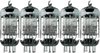
Yep, they are definitely 6AM6 tubes. Unfortunately I think I have cooked them- on closer inspection there is a blue stain through the tube that certainly wasn't there before. I did order some spares as I worked on the assumption the tubes that came in the Trimax were DOA.

I've got some spare 6AU6 tubes as well, so I might load up 4 6AU6 first, and test the unit, then worry about the 6AM6 tubes when it's working. I assume the tube swap is just a common mod to bump up the gain.

I've grabbed the pinouts from the National Valve Museum site, so I can work out what needs changing if I choose to use the 6AM6 type.
Alistair McLean
Alistair
Frequent Contributor
 
Posts: 634
Joined: Fri Jul 16, 2010 11:35 am
Location: Melbourne


Return to D.I.Y.

Who is online

Users browsing this forum: No registered users and 7 guests